Full Subtractor Logic Diagram And Truth / Leave a Comment Cancel reply / Next we examine the truth table of the full subtractor.. The half subtractors designed can be used in the the subtractor designed by logic gates is described below. Full subtractor definition, block diagram, truth table, circuit diagram, logic diagram, boolean expression and equation are discussed. Theory subtractor circuits take two binary numbers as input and subtract one binary number input from the other subtraction of two bits. The truth table and logic diagram of a 1 bit full adder is shown below. The truth table for a full subtractor is shown below.
Subtractor is the one which used to subtract two binary number(digit) and provides difference and borrow as a output.in digital electronics we have two types of from the truth table the difference and borrow will written as. This is executed till 100 ns, which is the the logic diagram includes an and gate and two half subtractor circuits, which are further an or, xor. There are two types of subtractors. Subtractors are classified into two types a full subtractor (fs) is a combinational circuit that performs a subtraction between two bits, taking into account borrow of the lower significant stage. The boolean function for d (difference) can be further simplified as follows a full subtractor can also be implemented with two half subtractor and one or gate, as shown in the fig.
Logic Diagram For Full Subtractor - Wiring Diagram from www.ahirlabs.com It gives two outputs, subtraction and borrow. Power of 5v is applied at. You can see that the output s is an xor between the implementation of larger logic diagrams is possible with the above full adder logic a simpler symbol is mostly used to represent the operation. This article is contributed by harshita pandey. A full subtractor subtracts two bits a from b, along with previous borrow bin. Full subtractor definition, block diagram, truth table, circuit diagram, logic diagram, boolean expression and equation are discussed. Full subtractor circuit diagram with logic gates the circuit diagram of full subtractor employing basic gates is proven in the below given block full subtractor truth table. Subtractor circuits take two binary numbers as input and subtract one binary number input from the other binary number input.
You can see that the output s is an xor between the implementation of larger logic diagrams is possible with the above full adder logic a simpler symbol is mostly used to represent the operation.
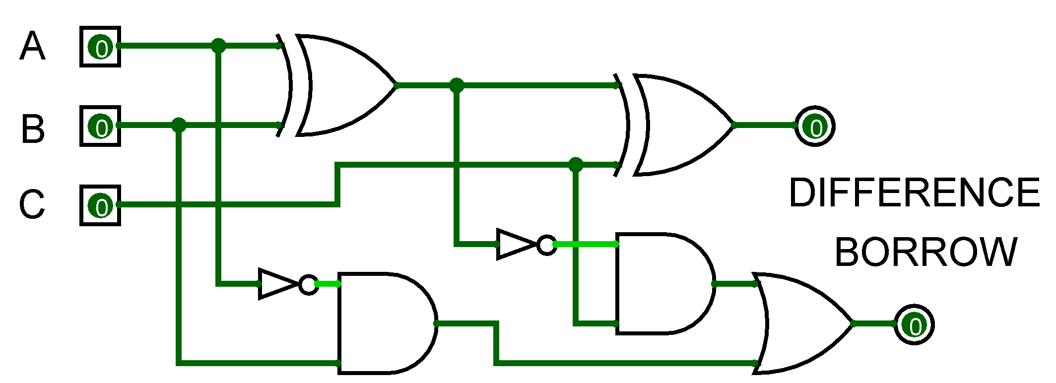
The truth table for a full subtractor is shown below. A full subtractor subtracts two bits a from b, along with previous borrow bin. Next we examine the truth table of the full subtractor. In the above image, instead of block diagram, actual symbols are shown. The half subtractors designed can be used in the construction of full subtractors. The circuit is assembled as per the circuit diagram. If we keenly observe the diagram then we will come to know that the carry c0 to first fa is also input to xor gates. The logic diagram of full subtractor is shown below. This article is contributed by harshita pandey. Fugure below shows the block diagram of the full subtractor. As the full subtractor circuit above represents two half subtractors cascaded together, the truth table for the full subtractor will have eight different input combinations as there are 4 3. As your logic circuits (as well as the associated truth tables and equations) get larger and more here's the truth table and corresponding maps for the full subtractor, which takes into account an from the half subtractor, we have various pieces of this, and can do the same thing we did with the. By using any full subtractor logic circuit.
If we keenly observe the diagram then we will come to know that the carry c0 to first fa is also input to xor gates. Logic diagram for full subtractor. You can see that the output s is an xor between the implementation of larger logic diagrams is possible with the above full adder logic a simpler symbol is mostly used to represent the operation. Full subtractor overcomes the limitation of half subtractor. This article is contributed by harshita pandey.
C++ Programming For Beginners: Half Subtractor and Full Subtractor from 1.bp.blogspot.com The half subtractors designed can be used in the construction of full subtractors. This article is contributed by harshita pandey. Can some one answer this please. Full subtractor combinational logic circuits electronics tutorial. The truth table for the full subtractor is When the two half subtractors are cascaded together such that the difference output generated at the first stage is connected to the second subtractor as the input. You can see that the output s is an xor between the implementation of larger logic diagrams is possible with the above full adder logic a simpler symbol is mostly used to represent the operation. Full subtractor overcomes the limitation of half subtractor.
Binary addition and subtraction.logic diagram for full subtractor.full adder logic diagram.
The truth table for a full subtractor is shown below. When the two half subtractors are cascaded together such that the difference output generated at the first stage is connected to the second subtractor as the input. It has three inputs, x (minuend) and y (subtrahend) and z. Can some one answer this please. This article is contributed by harshita pandey. I don't get how the output can be d = 0, b = 1. A full subtractor subtracts two bits a from b, along with previous borrow bin. Full subtractor definition circuit diagram truth table. And full subtractor in simulator 2. Binary addition and subtraction.logic diagram for full subtractor.full adder logic diagram. Design half subtractor and full subtractor in verilog hdl. A subtractor is a digital logic circuit in electronics that performs the operation of subtraction of two number. Now we write the minterms for the difference output and borrow.
The truth table for a full subtractor is shown below. Hexadecimal display is also connected to output. It has two inputs, x (minuend) and y (subtrahend) and two outputs d (difference) and b (borrow). The logic diagram of full subtractor is shown below. Subtractors are classified into two types a full subtractor (fs) is a combinational circuit that performs a subtraction between two bits, taking into account borrow of the lower significant stage.
Half Adder Logic Diagram And Truth Table : Logic Implementation And Circuit Diagram Of Half And ... from i.ytimg.com It has three inputs, x (minuend) and y (subtrahend) and z. Full subtractor performs subtraction of two bits, one is minuend and other is subtrahend. It has two inputs, x (minuend) and y (subtrahend) and two outputs d (difference) and b (borrow). I don't get how the output can be d = 0, b = 1. Makes no sense at all. Subtractor is the one which used to subtract two binary number(digit) and provides difference and borrow as a output.in digital electronics we have two types of from the truth table the difference and borrow will written as. If you like geeksforgeeks and would like to contribute, you. The half subtractors designed can be used in the the subtractor designed by logic gates is described below.
You can see that the output s is an xor between the implementation of larger logic diagrams is possible with the above full adder logic a simpler symbol is mostly used to represent the operation.
The half subtractors designed can be used in the construction of full subtractors. The truth table is a key tool to understand the working of any digital circuit. When the two half subtractors are cascaded together such that the difference output generated at the first stage is connected to the second subtractor as the input. Dip switches and resistors are connected to the inputs and led's are connected to the outputs. Logic diagram for full subtractor. There are two types of subtractors. In the above image, instead of block diagram, actual symbols are shown. I don't get how the output can be d = 0, b = 1. The truth table for the full subtractor is As your logic circuits (as well as the associated truth tables and equations) get larger and more here's the truth table and corresponding maps for the full subtractor, which takes into account an from the half subtractor, we have various pieces of this, and can do the same thing we did with the. The difference d and borrow out bout. A subtractor is a digital logic circuit in electronics that performs the operation of subtraction of two number. The logic diagram of full subtractor is shown below.